
The AFEA1001 inductive sensing technology
A sensing principle that removes every weak point of optical and magnetic encoders — self-developed, fully controlled, and ready to be customized around your product.
How eddy-current position sensing works
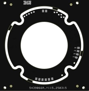
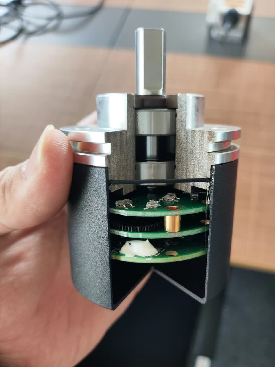
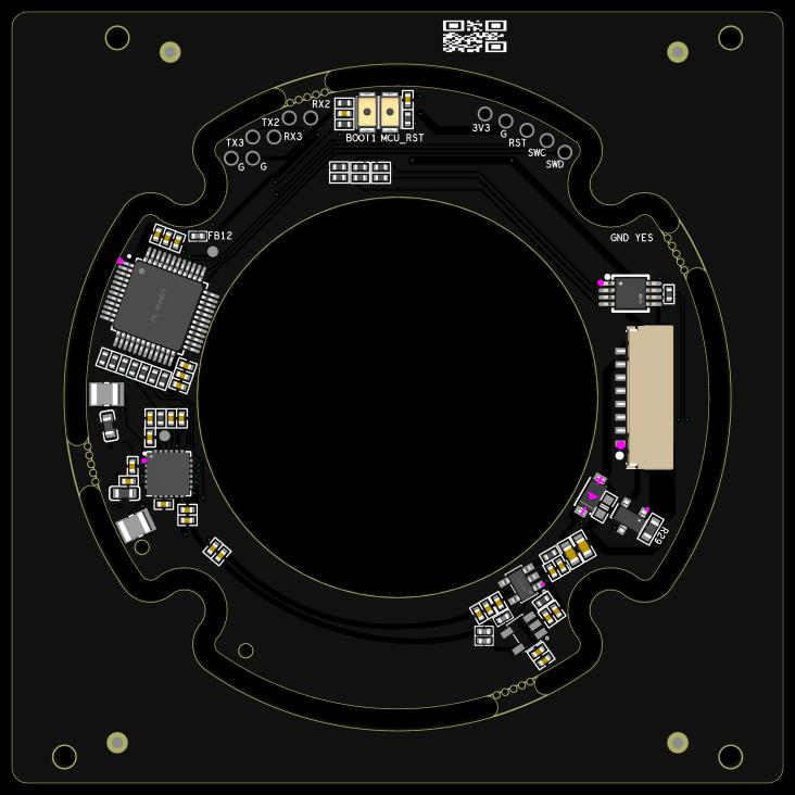
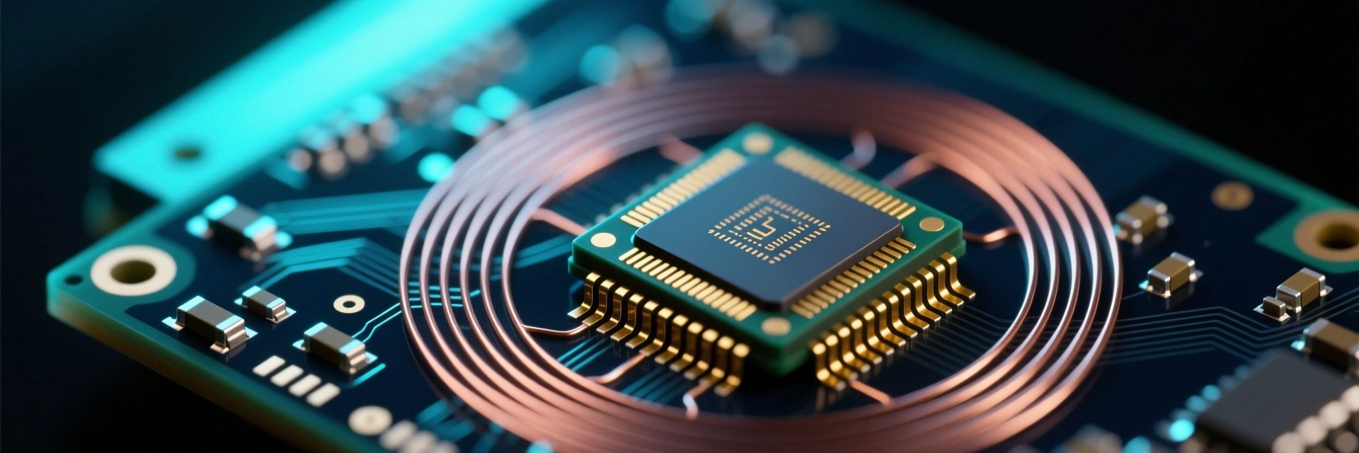
The AFEA1001 drives planar PCB coils with four inductive channels. When a metal target moves over the coil array, eddy currents change the coil's effective inductance. A high-speed 12-bit ADC samples this change and the on-chip ARM core computes absolute position — no optics, no magnets.
Drive
4 inductive channels fire sequentially at up to 100 MHz internal clock.
Detect
The metal target induces eddy currents that alter coil inductance.
Convert
12-bit SAR ADC samples the change at 1 Msps.
Compute
32-bit ARM Cortex-M0+ core calculates absolute angle or linear position.
AFEA1001 — a complete position sensor on one chip
Instead of buying off-the-shelf sensing chips, we designed our own. That means total control over cost, supply chain, performance and — most importantly for OEMs — the ability to customize the silicon itself.
| Inductive module | 4-channel coil driver, sequential mode, 100 MHz internal clock |
| CPU core | 32-bit ARM Cortex-M0+, 24 MHz, single-cycle 32-bit multiplier |
| Memory | 64 KB embedded Flash · 4 KB SRAM |
| ADC | 7-channel, 12-bit, 1 Msps SAR |
| Interfaces | UART / SPI / I2C / One-Wire and more |
| Security & traceability | 16-byte unique UID, Flash write-protection, encrypted debug port |
| Field upgrade | Embedded bootloader — firmware update over UART, even after sealed assembly |
| Reliability | LVD low-voltage detection · hardware CRC-16 |
| Supply voltage | 2.5 V – 5.5 V |
| Temperature | −40 °C to +85 °C |
| Low power | Deep Sleep < 1 µA |
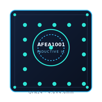
| Package | QFN24 · 4.6 × 4.6 mm |
One chip replaces both the sensing front-end and an external MCU — and because it is our own silicon, there is no imported-chip markup in the BOM. That structural cost advantage is why the RM series undercuts comparable imported encoders by roughly 40–60% without cutting performance, and why high-volume OEMs can customize at chip level (cost basis: our BOM structure; TCO analysis on request).
Why inductive beats optical and magnetic
| Property | Inductive (Luoyun) | Optical | Magnetic |
|---|---|---|---|
| Dust / oil / water resistance | Immune — sealed PCB coils | Sensitive — contamination blocks light | Good |
| Magnetic interference immunity | Excellent — works next to motors | Good | Sensitive — magnets can shift |
| Aging & wear | No LED aging, no mechanical wear | LED output degrades over time | Magnet strength drifts |
| Temperature range | −40 ~ +85 °C | Typically 0 ~ +70 °C | −20 ~ +70 °C |
| Component cost | 30–50% lower than optical | High | Low |
| Output & accuracy | Absolute · 0.001° / 0.03 µm | Absolute (high-res) | Absolute |
| Weight & size | Light, compact PCB-based | Bulkier optics | Compact |
What the technology unlocks for your product
Field reliability
Encoders fail in the field mostly from contamination and aging. Inductive sensing eliminates both failure modes.
Robot joints
Humanoid and cobot joints pack motors, gears and magnets in tight spaces — exactly where magnetic immunity matters.
Battery power
Deep Sleep under 1 µA at the chip and under 2 µA at the encoder makes battery-powered meters practical.
Custom silicon
Because the ASIC is ours, we can tune functionality for your application — a level of customization most encoder buyers never get.
Want the technical deep dive?
Request our engineering white paper on inductive sensing design, coil layout and protocol implementation — written by the engineers who built the IC.